Mapping our research aircraft’s boundary layer
The FAAM Airborne Laboratory, which is managed by the National Centre for Atmospheric Science, commissioned BAE Systems to complete a Computational Fluid Dynamics analysis project of our research aircraft.
The project, which is part of the research aircraft facility’s Mid-Life Upgrade programme, provides the facility with a visualisation of the research aircraft’s boundary layer, and a better understanding of aircraft drag, performance, and optimal instrument placement. The Computational Fluid Dynamics analysis project is key to tackling the aircraft’s challenges of sampling gases and particles in the sky.
Challenges of sampling from undisturbed air
The FAAM Airborne Laboratory enables environmental scientists to fly research instruments up into the skies to take in-situ measurements of the atmosphere.
This data is used to better understand our weather, climate change and air pollution, monitor and respond to natural disasters or environment-impacting emergencies, and track emissions from human activities.
Atmospheric data comes in a lot of different forms. We might look at aerosols, fine particles suspended in the air, or we might be studying the chemicals found in the atmosphere (both natural and human-caused).
We can capture the microscopic particles that lead to the formation of clouds, and record the ambient air currents where we’re flying. Collecting this data in an aircraft that weighs over 40 tonnes and flies at speeds of more than 250 mph is challenging.
Atmospheric measurements need to come from undisturbed air for scientists to gain an accurate understanding of our atmosphere. But aircraft disrupt the atmosphere as they fly through it – pushing air aside, creating turbulence, and leaving swirling vortices in their wake.
The separation between the air disturbed by an aircraft’s flight and the undisturbed air beyond is called the boundary layer. The boundary layer fluctuates in depth depending on an aircraft’s shape – it is thinnest at the aircraft’s nose, and expands out into a swirling wake of turbulence as it passes over the rest of the aircraft towards the tail.
“The instruments that we use to measure the atmosphere on our aircraft need to be carefully positioned to capture air outside the boundary layer. The boundary layer is thicker nearer the aircraft’s tail, so many of our external instruments and inlets are positioned closer to the aircraft’s nose,” explains Stephen Devereau, Mid-Life Upgrade Project Director at the FAAM Airborne Laboratory.
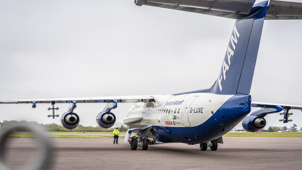
Because the FAAM Airborne Laboratory is specially modified for its purpose as an atmospheric research aircraft, it has several features that are not found on many other planes – such as its large radiation blister and the instrument pylons on the wings.
Each of these creates further changes to the aircraft’s aerodynamics, so it is important we know what impact they will have on the boundary layer.
Another challenge to take into consideration is how we fly. The FAAM Airborne Laboratory is capable of sustained flight at 100 feet, and at comparatively low speeds. To achieve this safely the aircraft must be flown with its nose slightly pitched up, which alters the airflow around the aircraft.
Visualising the boundary layer around the aircraft
As part of the research aircraft facility’s Mid-Life Upgrade, a five-year project to improve performance and capabilities while reducing environmental impact, a Computational Fluid Dynamics (CFD) analysis project has been completed by BAE Systems.
Stephen Devereau describes the importance of the work: “The CFD project brings new modelling tools to the research aircraft facility, and the wider science community. BAE Systems was commissioned to further develop and apply their own CFD tools to suit the FAAM Airborne Laboratory and assist with related instrument development.”
BAE Systems created a unique CFD analysis of our research aircraft, which took into account our specialised flight profiles and externally-mounted instruments.
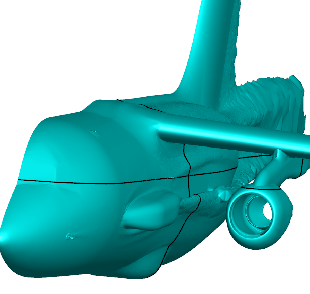
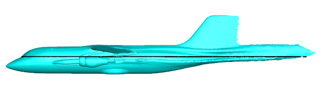
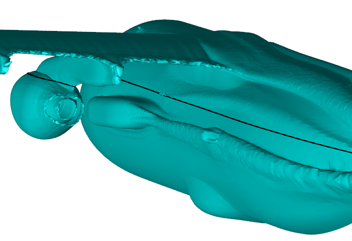
The CFD analysis has modelled the boundary layer of our research aircraft, and will enable the team to position new instruments where there is less interference with, or impact from, existing mounted instruments. The CFD tool will also provide useful insights when making improvements to overall aircraft drag and performance.
The CFD analysis by BAE Systems has produced a range of images that show the boundary layer of the FAAM Airborne Laboratory’s research aircraft: